UNREAL ENGINE 5.8 · CHAOS VEHICLE · CONTROL RIG · PYTHON

ZIS-42 Half-Track

A drivable WWII half-track with a 65-pad procedural track that conforms to terrain in real time. The suspension is driven by the vehicle's actual Chaos physics rather than by raycasts, and a least-squares fit across the road wheels turns those forces into bogie rock, rocker articulation and body motion. No baked animation anywhere — every frame is solved live by the Control Rig from physics and player input.

Build time
~20 hours end to end
Custom tooling
Maya track-loop setup tool
Pads per side
65
Baked keys
0
Shot by shotWhat to watch
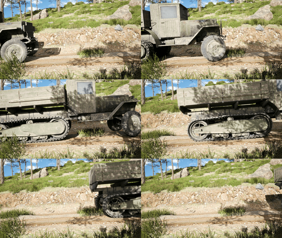
Track pass 01
Track pass

Pads advancing by distance travelled — the belt station wraps seamlessly, never slipping against the sprocket.
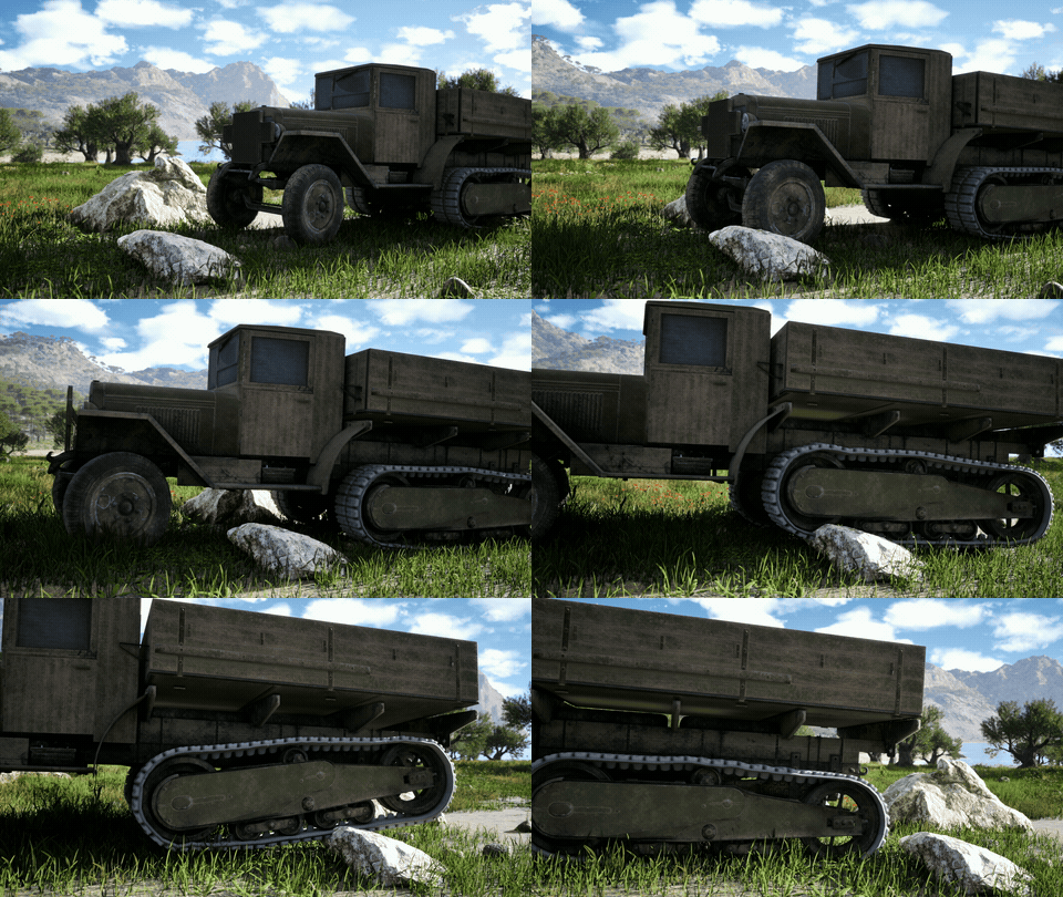
Side profile over rock 02
Side profile over rock

Road wheels ride up the boulder while the hull holds its line — bogie rock and rocker residual doing the work.
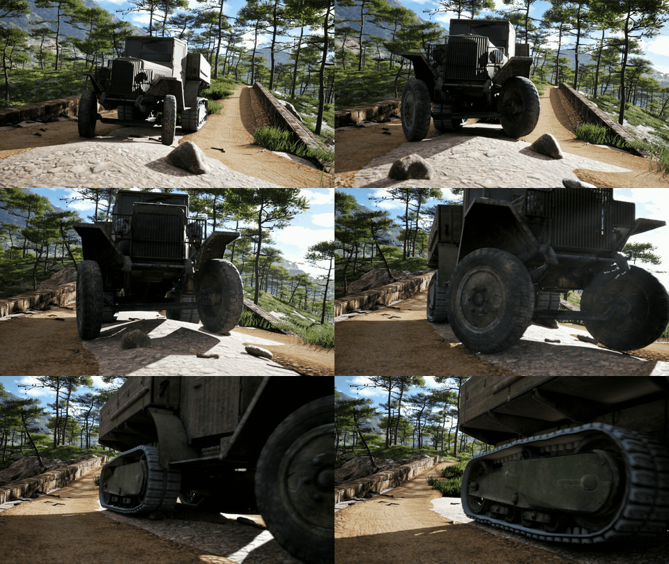
Front approach 03
Front approach

The solid beam axle: average offset lifts the hinge, the difference rolls it, both wheels inherit the roll.
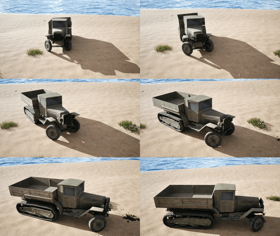
Beach pass 04
Beach pass

Soft, even ground — baseline read on ride height after the body levelling pass.
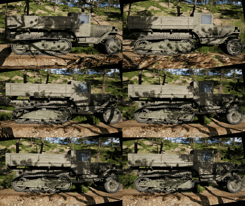
Dolly alongside 05
Dolly alongside

Full 65-pad loop in profile: one distance accumulator drives both belt and wheel spin.
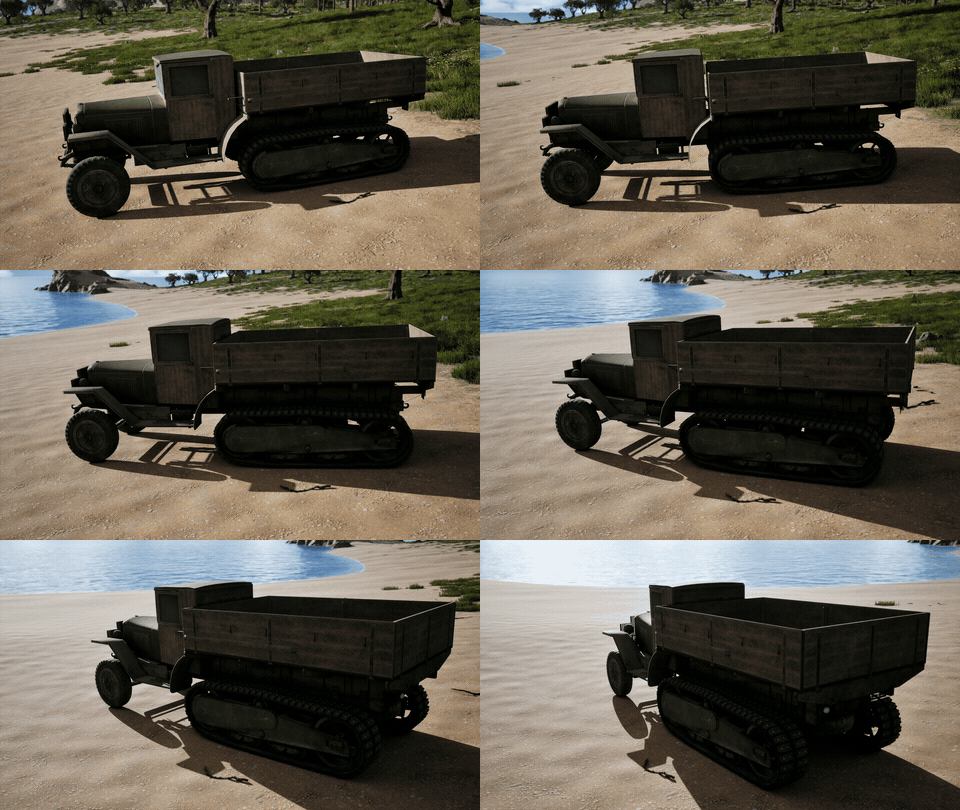
Orbit at rest 06
Orbit at rest

Static pose — bogie, rockers and track settled on the Chaos suspension offsets.
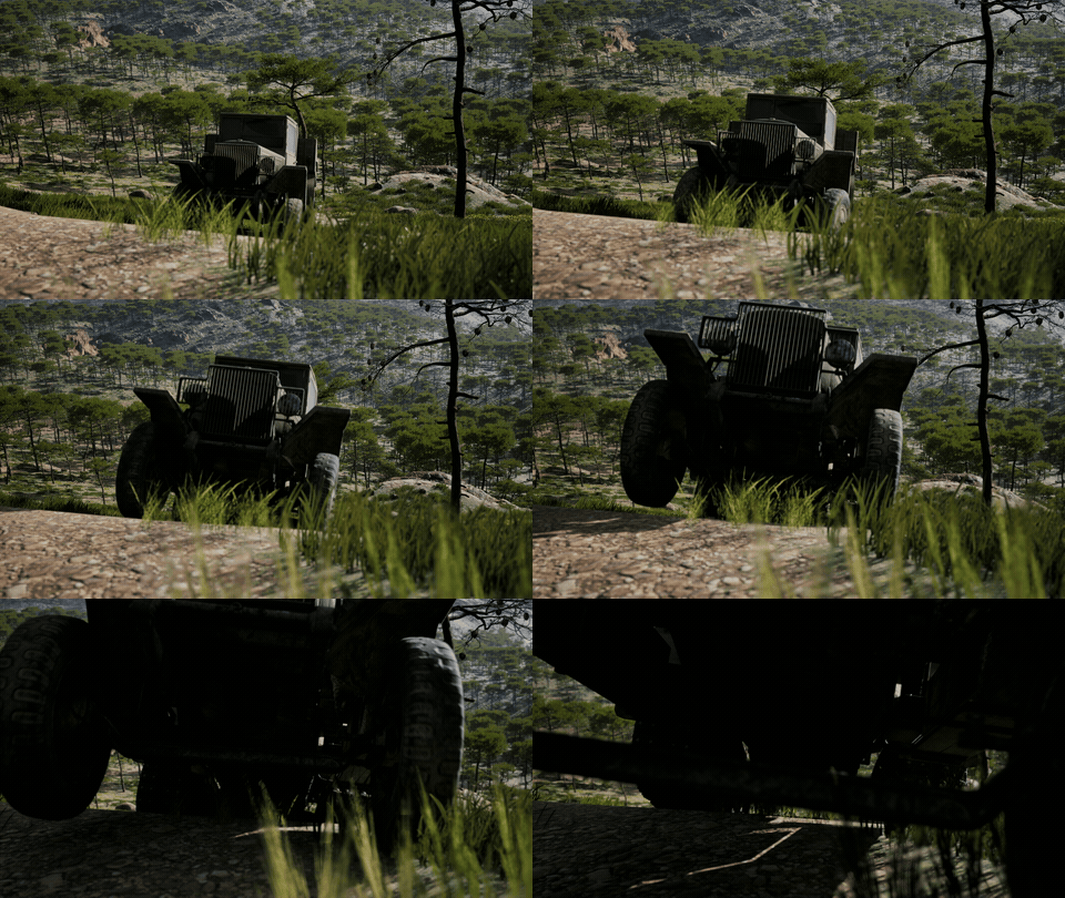
Ridge close pass 07
Ridge close pass

Uneven terrain into camera; watch the cargo bed's under-damped springs overshoot and settle.
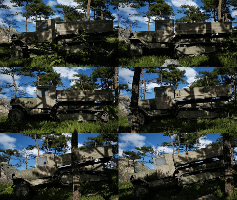
Hero profile 08
Hero profile

The reel's closing beat — no baked keys anywhere in frame.

How it works
01
Procedural track belt

65 pads per side, positioned each frame by station along a closed spline. A pad's station advances with distance travelled and wraps at 0–1; its position is a lerp between the two nearest control points, rotation taken from the segment tangent. The belt is a rigid loop transformed by the bogie — the conform comes from the bogie and rockers moving, not from pads deflecting individually. One distance accumulator drives both belt and wheel spin, so they can never desync.

02
Physics-driven suspension

Each road wheel's vertical offset comes from the Chaos wheel's own GetSuspensionOffset, passed through the Anim BP into the rig. Nothing in the rig raycasts the world — the visual suspension is a readout of the simulation actually driving the vehicle, so the wheels can't disagree with the physics.

03
Bogie solve

The four road-wheel offsets per side feed a least-squares slope fit whose lever arms come from the real bone positions (±56.5 cm and ±18.4 cm about a centroid 107.5 cm behind the pivot). The fit yields the bogie rock angle; each wheel's leftover residual drives its rocker as a see-saw. A single wheel meeting an obstacle rotates its rocker while the hull stays level, rather than heaving the whole assembly.

04
Solid front axle

A genuine beam axle: the average of the two wheel offsets lifts the front hinge, the difference rolls it, and both front wheels inherit that roll.

05
Body & secondary motion

The physics chassis rides ~12 cm high because the road wheels droop to reach the ground, so a levelling pass re-plants the body at bind height while wheels and track stay on the floor. Above that, the cargo bed carries input-driven secondary motion — throttle tips it back, braking dips it forward, steering leans it, sharp wheel movement adds a capped vertical pop — on deliberately under-damped springs so they overshoot and settle.

06
Tooling

Authored and tuned entirely through Python-driven remote execution against a live editor. Every parameter pass is scripted, idempotent and reversible, and the graph self-documents via generated comment blocks. A companion Maya tool builds the track loop itself — laying out the pad chain and its control points so the belt can be rebuilt or re-fitted in minutes rather than by hand. About 20 hours of work in total to get the rig to where it is now.

Custom tooling — Maya track loop builder

Building the loop is the slow part — so I automated it

Laying out 65 pads and their control points by hand is hours of work, and any change to the sprocket, idler or wheel spacing means doing it again. This Maya tool generates the whole chain from the wheel positions: it builds the closed path, distributes the pads evenly along it, and outputs the control points the Control Rig reads at runtime.

Re-fitting the belt after a geometry change drops from an afternoon to a couple of minutes, which is what made iterating on the suspension practical at all.

ZIS42_ControlRig — belt station & bogie fitUE5 · PSEUDO
station  = frac(station0 + distTravelled / beltLength)
seg      = station * numPoints
pad.T    = Lerp(P[floor(seg)], P[ceil(seg)], frac(seg))
pad.R    = LookAt(P[ceil(seg)] - P[floor(seg)])

# offsets read from Chaos, never traced
z        = [ChaosWheel[i].GetSuspensionOffset() for i in Side]
slope, _ = LeastSquares(leverArms, z)   # +/-56.5, +/-18.4
bogie.Rock       = atan(slope)
rocker[i].Angle  = (z[i] - slope * leverArms[i]) * rockerGain
body.Z          -= chassisDroop            # re-plant at bind
← Back to portfolio sunsarith96@gmail.com